
Take control of your next loudspeaker project. The Audio Products LR24 family brings analog active crossover filtering to your own system, with adjustable crossover points, driver-level matching and optional signal-processing boards.
Build a 3-way loudspeaker, a 2-way system or a 2-way setup with a subwoofer output. Filtering takes place before the power amplifiers, giving each driver its own frequency band and amplifier channel.
From filter boards and resistor banks to power supplies and connector panels, create a combination that fits your drivers and your ambitions.
Select the board revisions, accessories and supplies that suit your chosen configuration.



The fourth-order Linkwitz–Riley topology provides a 24 dB/octave asymptotic roll-off. Its complementary outputs are each −6 dB at the crossover frequency and sum flat under ideal level and phase conditions.
Use this electrical foundation to develop the acoustic response you want: measure the drivers, account for their offsets and enclosure behaviour, then refine levels and phase around the crossover points.
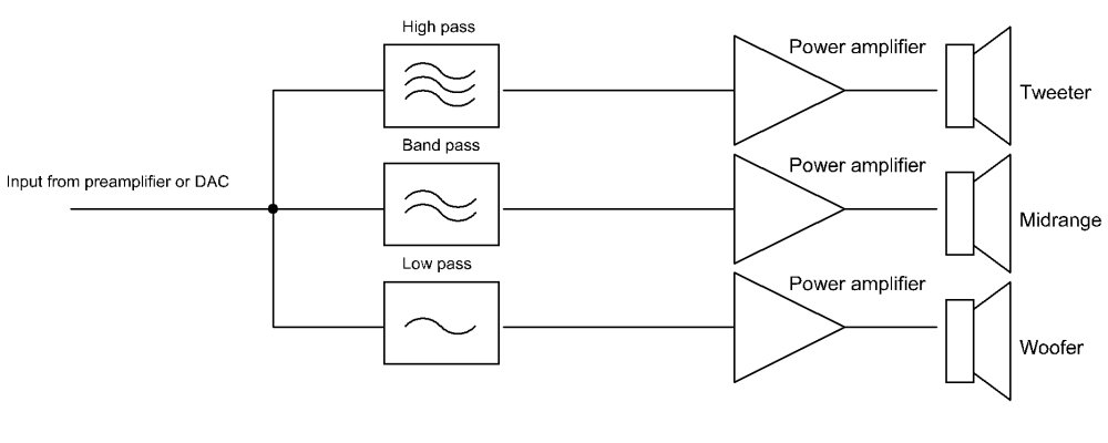
The diagram shows the three-way signal path: separate low-, mid- and high-frequency bands, each feeding its own power amplifier and driver.
Verify filtering before connecting vulnerable drivers. A series capacitor can provide DC blocking when selected for the driver impedance and intended response; include appropriate amplifier protection as part of the complete design.
Technical background: Linkwitz Lab: active filters.
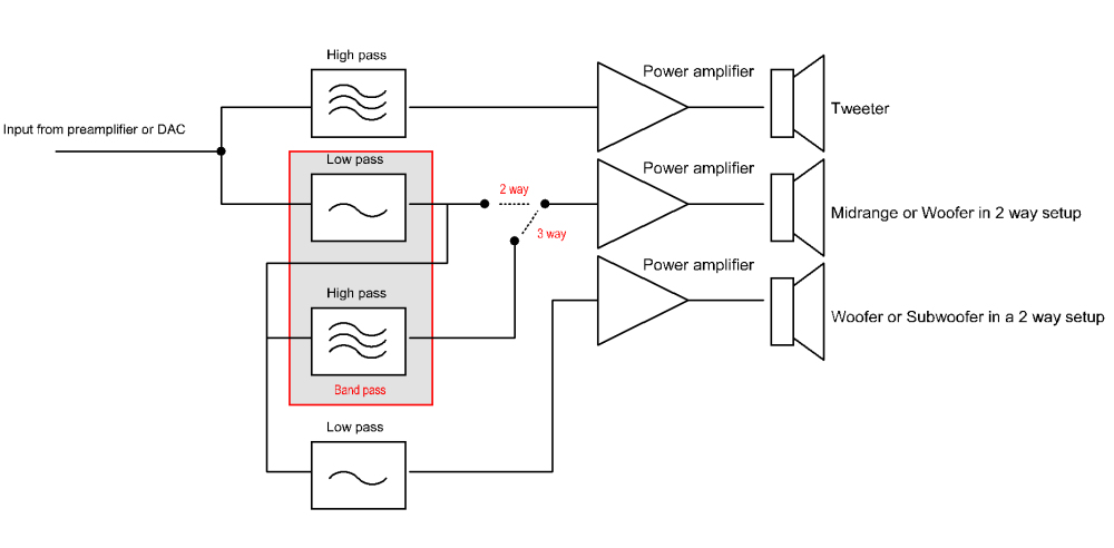
The upper crossover divides the tweeter band from the lower-frequency signal. A second stage divides that lower signal into midrange and woofer bands.
The main high-pass and low-pass outputs serve the tweeter and woofer. Configure the board according to its documentation for this mode.
The main crossover serves the two-way loudspeaker, while the additional low-pass path provides the subwoofer output. Check the main speakers’ low-frequency response when integrating the subwoofer.
Two plug-in resistor banks make it practical to adjust crossover frequencies without changing the main PCB. Explore settings for your driver combination and refine the response as your project develops.
An upper crossover at 6,000 Hz and a lower crossover at 600 Hz illustrates the two settings. These are examples, not recommendations for every driver combination.
A main crossover at 2,500 Hz and subwoofer low-pass at 150 Hz illustrates this arrangement. Select actual frequencies from driver measurements, usable bandwidth and power handling.
The described circuit provides output attenuation from 0 to −12 dB for level matching, together with balanced and unbalanced outputs for the amplifier connections.

Plug-in headers support optional notch, phase-correction and equalization circuits. Choose and adjust these from the measured loudspeaker response.

Combine two crossover boards, the matching supply arrangement, transformers and a system controller for a complete stereo project.
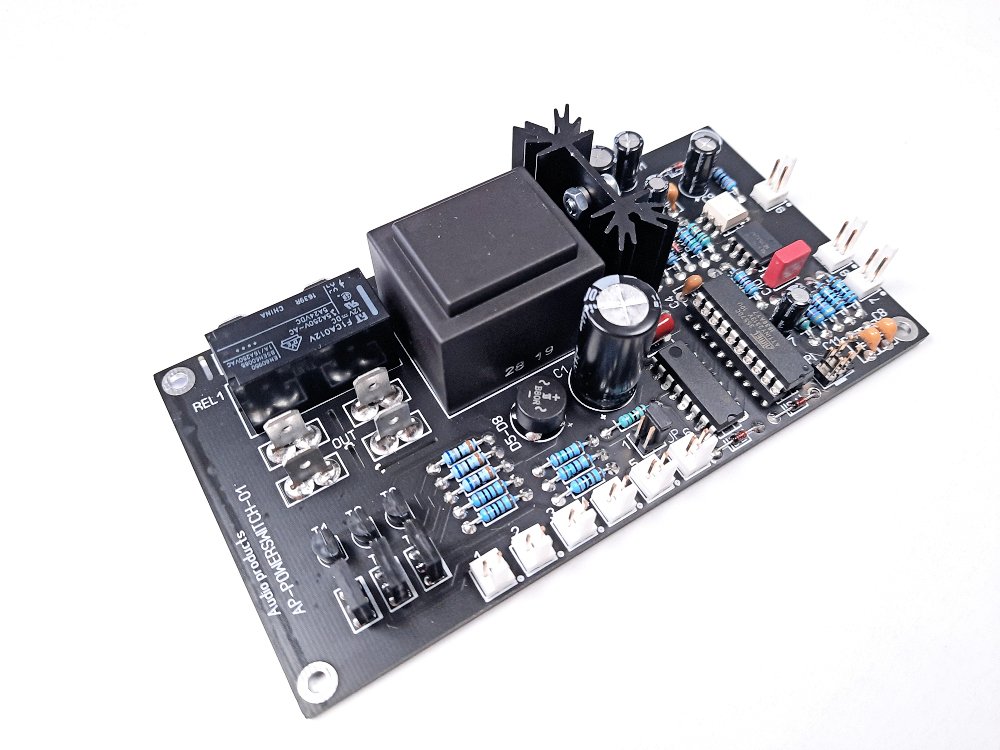
The controller sequences three amplifier trigger lines at approximately one-second intervals, spreading start-up across the system. Choose momentary push-button control, a compatible trigger input or optional audio detection to suit your listening setup.
With audio detection configured, the system can switch on when music is present and return to standby after about 15 minutes without a detected signal. Separate filter and output-stage supply connections support a considered supply and grounding layout.
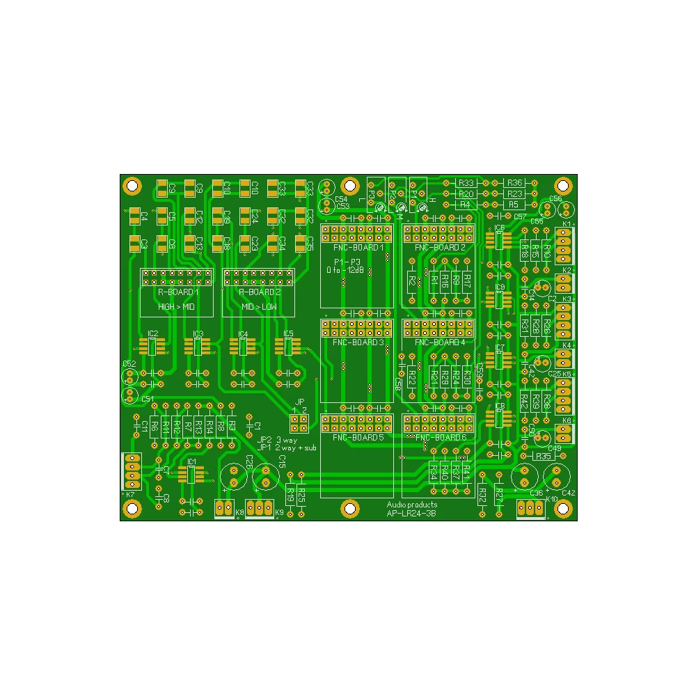
The LR24-3B PCB accommodates Texas Instruments OPA1602 or OPA1612 audio op amps. Check the selected product version when ordering.
It provides a balanced input and buffered balanced and unbalanced outputs with separate headers. Follow the board documentation when connecting an unbalanced source.
A controller connection provides an audio-detection signal for automatic system operation.
Two supply inputs allow the filter and output stages to be supplied separately.
In 3-way operation, one resistor bank sets the high-to-mid crossover and the other sets the mid-to-low crossover.
In 2-way-plus-subwoofer operation, the second bank sets the subwoofer low-pass frequency.
Select the resistor-bank boards separately to match your required crossover frequencies and PCB version. This gives you the flexibility to configure the filter around your chosen loudspeakers.

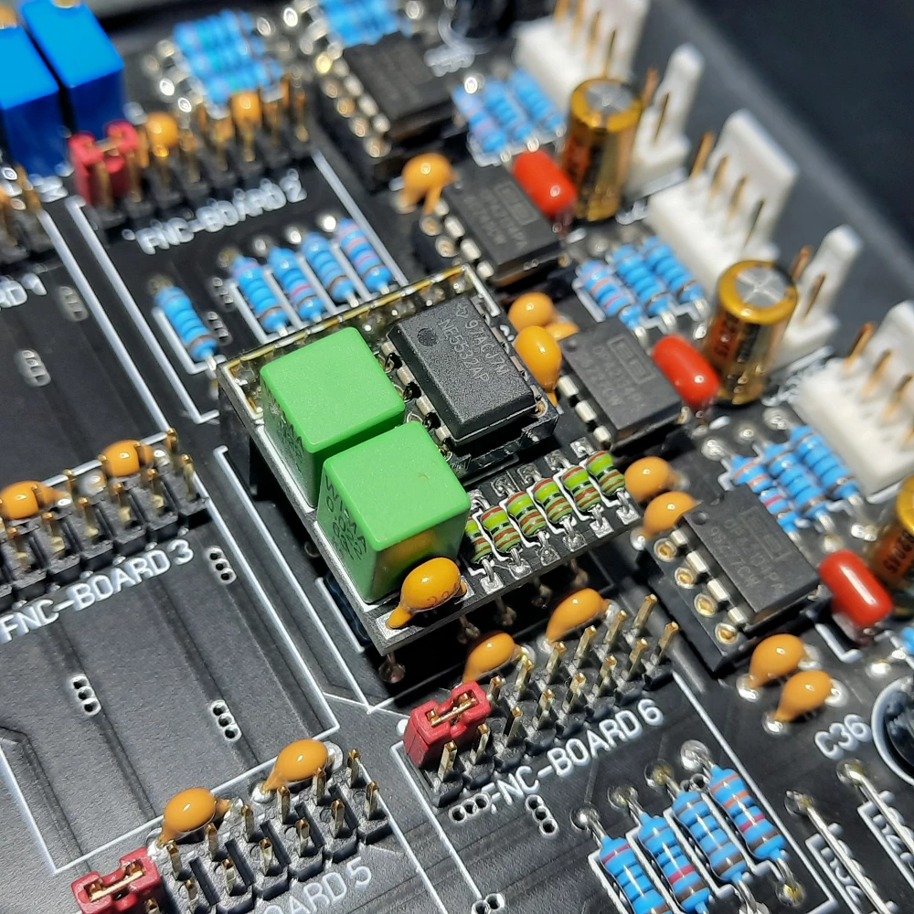
Optional phase-correction boards give you another way to refine driver integration around the crossover region. The illustrated module provides two first-order allpass sections that can be used separately or in series.
Use measurements to choose the correction for your loudspeaker. Each section adjusts phase with frequency-dependent group delay, allowing targeted tuning around the crossover.
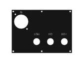
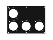
Three audio panel arrangements are illustrated. Check the selected panel’s connector set, supplied wiring and fit with your enclosure.
XLR input + RCA outputs: for unbalanced amplifier connections.
XLR input + XLR outputs: for balanced amplifier connections.
XLR input + XLR and RCA outputs: both output connection types.
Balanced-to-unbalanced wiring: follow the circuit-specific connection diagram. Do not assume XLR pin 3 can be left unconnected in every input circuit. Correct signal-return and shield connections depend on the equipment.
Reference: Rane: Sound System Interconnection.
A separate controller panel provides mains and trigger connections. Check the module’s ratings and wiring instructions before installation.
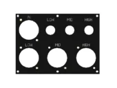
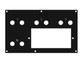


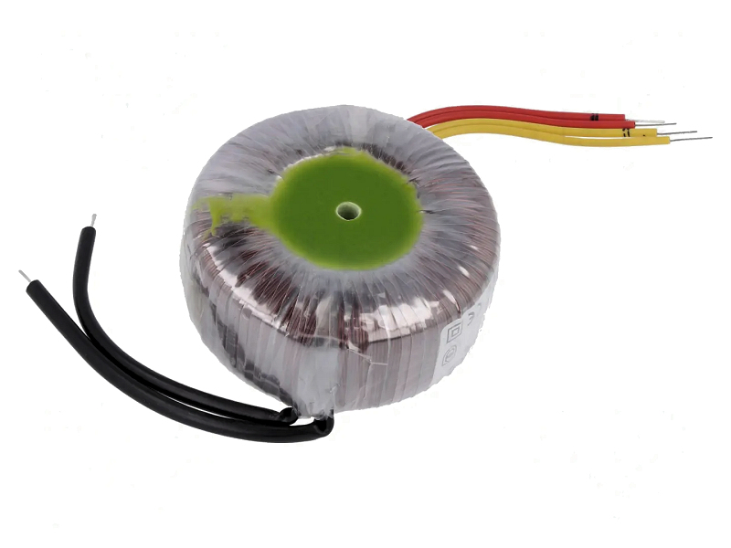
The PSP05 is designed to supply two crossover boards through four output connections, separating the filter-stage and output-stage feeds. Follow the matching board and power supply diagrams for the exact connections and polarity.
Bring local switching, audio detection and compatible amplifier trigger outputs together with a matching controller. Plan the switching sequence as part of your system.
A stereo 3-way system normally needs six amplifier channels. Plan gain, noise, grounding and enclosure wiring as part of the complete system.
Share your drivers, intended configuration and amplifier models. We can help you choose the crossover, resistor banks and accessories for your next project.